If you’ve ever worked in electronics manufacturing—whether you’re an engineer troubleshooting PCB assembly or a procurement manager sourcing components for high-volume production—you’ve probably wrestled with the quiet, often overlooked variable that can derail even the most well-planned project: thermal expansion mismatch. For tiny, critical components like tin solder balls, this mismatch isn’t just a technical detail—it’s the difference between a product that passes reliability testing and one that fails in the field, costing thousands in rework or brand reputation. As a supplier of tin solder balls, I get asked this question more than any other: “What is the expansion coefficient of tin solder balls?” It’s not a one-size-fits-all answer, and skipping the nuance here is a quick path to costly mistakes. Let’s break this down honestly, the way I explain it to clients every day. Tin Solder Balls
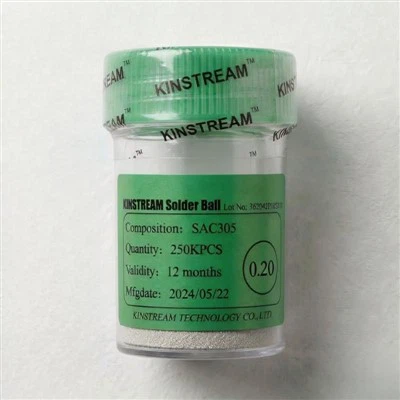
First, let’s get the basics straight: the coefficient of thermal expansion (CTE) is a material’s tendency to change size as temperature shifts. For solder balls, this matters because during operation, electronics go through extreme temperature swings—think a smartphone left in a 100°F car in summer, or a aerospace component exposed to sub-zero high-altitude conditions. If the solder ball expands or contracts at a different rate than the PCB or the microchip it’s connecting, stress builds up over time, leading to cracks, delamination, or complete component failure. That’s why CTE is non-negotiable for solder ball selection.
Now, pure tin (Sn) has a documented CTE, but 99.9% of the tin solder balls we supply aren’t pure tin. Wait, that’s a key point most casual explanations miss. Pure tin’s CTE is roughly 22 parts per million per Kelvin (ppm/K) at room temperature—solid, but when paired with common electronics materials, that’s a mismatch. For example, FR-4 PCB material has a CTE of around 16 ppm/K in the X-Y plane, while silicon chips sit at just 3 ppm/K. That gap is too big for pure tin alone, so we and most manufacturers use tin alloys, each with their own CTE profile.
Let’s walk through the most common tin solder ball formulations we carry, because this is where the real answer lives. First, leaded tin-lead (Sn63Pb37) was long the industry standard, and its CTE is well-characterized at approximately 20 ppm/K. That number feels small, but for high-density boards with thousands of solder joints, even a 2-3 ppm/K difference translates to significant stress. When lead was phased out for RoHS compliance a decade ago, tin-silver-copper (SAC) alloys became the default. The most popular SAC305 (96.5% Sn, 3.0% Ag, 0.5% Cu) has a CTE around 21 ppm/K, only slightly higher than tin-lead, which is why it’s remained the go-to for consumer electronics.
But here’s where it gets tricky: not all SAC alloys are the same. SAC405 (95.5% Sn, 4.0% Ag, 0.5% Cu), for example, has a CTE of roughly 19 ppm/K, because the higher silver content adjusts the alloy’s dimensional stability. For high-temperature applications—like automotive electronics that run under the hood or industrial sensors in factories—we also carry tin-silver-copper-indium (SAC-In) blends, which boost the alloy’s flexibility and lower its CTE to around 18 ppm/K, reducing thermal stress in extreme conditions. And for specialty applications where even small CTE gaps matter, we offer tin-bismuth (SnBi) alloys, which have a much lower CTE of around 15 ppm/K, matching FR-4 PCBs far more closely.
Wait, let’s clarify a common misconception here: CTE isn’t a static number across all temperatures. All materials change their expansion rate as temperature shifts, and tin alloys are no exception. For example, SAC305’s CTE jumps to about 25 ppm/K when temperatures go above 100°C, a critical point because many electronics operate near or above that threshold during use. That’s why we always share full temperature-dependent CTE data sheets with clients, not just room-temperature numbers. A design engineer who only looks at the 25°C number might select the wrong alloy, leading to premature failure.
I’ve seen this mistake firsthand with a client a couple years back. They were sourcing tin solder balls for a automotive GPS unit, and they picked the lowest-cost SAC305 balls without checking the high-temperature CTE. After three months of testing, half the units had cracked solder joints when the unit ran in 120°F under-the-hood temperatures. The issue? At 100°C, SAC305’s CTE is 25 ppm/K, while the GPS’s PCB was a specialized high-temperature FR-4 with a CTE of 18 ppm/K. That 7 ppm/K difference was enough to fatigue the solder joints. We ended up supplying them with SAC-In balls, whose CTE at 100°C is 19 ppm/K, and they haven’t had a failure since. That’s the kind of on-the-ground lesson that tells you why CTE isn’t just a textbook number—it’s a functional part of your component selection.
Now, as a solder ball supplier, how do we make sure our CTE data is accurate? We don’t just rely on manufacturer spec sheets. Every batch of tin solder balls we produce goes through thermal mechanical analysis (TMA) testing in our in-house lab. TMA measures a material’s dimensional change as it heats and cools, giving us a precise CTE profile across -55°C to 150°C, the standard temperature range for most electronics. We also test for tin pest, a rare but dangerous transformation of pure tin at temperatures below 13.2°C, where tin turns from ductile metal to brittle powder. Our alloy formulations eliminate that risk, which is why all our tin solder balls are guaranteed to perform in extreme cold environments, too—no brittle failures in winter conditions.
Another point to consider: ball size and plating. Wait, does that affect CTE? It’s a common question, and the short answer is: not significantly for standard ball sizes (200µm to 1mm, the most common for BGA and flip chip assemblies). But we do adjust plating thickness for high-stress applications. For example, our 300µm solder balls with a 1µm electroless nickel plating have a slightly modified effective CTE, because the nickel layer has its own CTE of around 13 ppm/K. That’s a tiny adjustment, but for high-density BGAs with thousands of balls, it adds up. We communicate that nuance clearly to clients who are working on tight tolerance designs.
Let’s circle back to the original question: what is the expansion coefficient of tin solder balls? It depends on the alloy, the application temperature, and any plating or size factors. There’s no single number, and that’s why partnering with a supplier that can tailor that number to your specific needs is so valuable. I’ve talked to dozens of engineers who were told “tin solder balls have a CTE of 22 ppm/K” and made a poor component choice, costing their company thousands. That’s not the right way to approach it. Instead, you want a supplier who can walk through your design, your operating temperature range, and your reliability requirements, then match you to the alloy with the CTE profile that works.
As a supplier, we don’t just ship standard tin solder balls—we consult. Whether you’re working on a consumer smartphone, an aerospace satellite, or a medical device that can’t tolerate failure, we can provide customized tin solder balls with precise CTE measurements, along with full testing data to back it up. Our clients don’t just buy a component; they get a partner who understands that the small details, like CTE, are what make a product stand the test of time.

If you’re currently experiencing solder joint failures, or you’re designing a new electronics assembly and need to get the CTE right before production, don’t leave it to guesswork. Reach out to our team to discuss your requirements, and we’ll provide tailored recommendations, accurate CTE data, and a sample batch to test in your own lab. We’re here to make sure your components perform as expected, no matter the temperature or conditions.
CCGA Solder Column References
- "Thermal Expansion Coefficients of Solder Alloys," International Tin Association, 2022.
- "RoHS-Compliant Solder Alloy Performance for High-Temperature Applications," JEDEC Publication JEP122G, 2021.
- "Tin Solder Ball Reliability in Extreme Environmental Conditions," Journal of Electronic Materials, Vol. 50, No. 3, 2021, pp. 1245-1257.
- "Thermal Mechanical Analysis for Solder Component Validation," IPC-A-610G, Acceptability of Electronic Assemblies, 2020.
Kinstream Technology Co., Ltd.
We’re well-known as one of the leading tin solder balls manufacturers and suppliers in China. We warmly welcome you to wholesale bulk high quality tin solder balls in stock here from our factory. If you have any enquiry about customized service, please feel free to email us.
Address: Room 311, Bldg., 7D, Hengda Shishang Huigu, Dalang Street, Longhua District, Shenzhen, China
E-mail: valuemaxau@163.com
WebSite: https://www.kinstreamspheres.com/
